This tool may be activated by clicking
the ![]() icon below the Selection Toolbar or by using the
Right-Click menu from within a model view. The
tool is only available from within a model view that has active results
for a single combination or a batch solution. This
tool is not available for an envelope solution.
icon below the Selection Toolbar or by using the
Right-Click menu from within a model view. The
tool is only available from within a model view that has active results
for a single combination or a batch solution. This
tool is not available for an envelope solution.
The Internal Force Summation Tool can be used to quickly come up with information on story shears in a building, or internal moments in a elevated or on grade slab.
When initiated, the tool requires the
user to select two points (A and B). These
points will be used to define the plane in which the internal force summation
will be performed. That defines a "cutting plane" perpendicular to the screen.

Clicking on a third point will lock the cutting plane to that exact location and provide a detailed summary of the internal forces at that location. These summary results are summarized below:
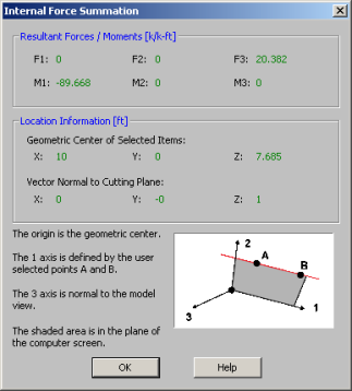
The Internal Force Summation report is separated into three regions. The first region gives the resultant forces and moments. The second region gives information needed to locate the reference plane and origin of local axes. The third region gives a basic reference for the orientation of the local axes and forces.
Since the Forces and Moments are summed only for the selected members, this tool can be easily used to determine the overall story forces in a shear wall or moment frame (if the whole model is selected), as well as the forces in an individual bent or pier (if only a portion of the model is selected).
The Geometric Center of the Selected Items defines the origin at which the forces (F1, F2, and F3) are reported. This also corresponds to the point used to define the moments (M1, M2 and M3). These forces and moment are all given with respect to the local 1, 2, 3 axes. The local 3 axis is always perpendicular to the current model view. The local 1 axis is always defined parallel to the points A and B which were are selected by the user. The 2 axis is then defined by the right hand rule.
Note:
 button. This button is intended to be used by clicking two points in the same plane as a wall panel (or a group of co-planar wall panels).
 button. This button is intended to be used by clicking two points in the same plane as a slab (or a group of co-planar slabs). Semi-rigid slabs are elements found in RISA-3D in a combined RISAFloor-RISA-3D model with slab floors.
 When cutting through a plate, the internal force summation tool uses the plate corner forces to derive the force in the cutting plate. When cutting through the interior of a plate, any corner node that is "above" the cutting plane is included in the summation. Moments are then interpreted based on the location of the forces compared to the centroid of the cutting plane. See the figure below:
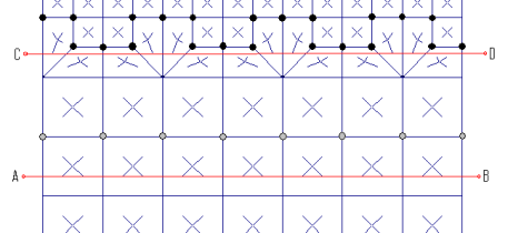
Consider the cutting plane A-B defined above. This was created by clicking from left to right on the page (from A to B). Therefore, there are 8 nodes above cutting plane A-B. These are highlighted in a gray color and are the nodes whose corner forces will be used to create the base value of the cutting plane force. Because the cutting plane is below the row of nodes, and because there may be applied surface or self weight loading at the plates, some interpolation must used between the values above the plane and the values below the plane. This consists of essentially a linear interpolation.
For cutting plan C-D there are 22 nodes above the cutting plane that will be used to determine the base value of the cutting plane force.
Note
 icon). If the model has not been run and there are no results, then the tool will be unavailable. Similarly, the tool is not available with Envelope Results.
 This tool may be activated by clicking
the  icon below the Selection Toolbar or by using the
Right-Click menu from within a model view and selecting Make a Cut Over Displayed Contour. The
tool is only available from within a model view that is currently plotting a
icon below the Selection Toolbar or by using the
Right-Click menu from within a model view and selecting Make a Cut Over Displayed Contour. The
tool is only available from within a model view that is currently plotting a
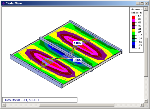

The Contour Display Detail is used to turn a visual plate contour into a more traditional shear or moment diagram. The tool merely transforms the visual contour display into actual numerical that can be viewed by the user. In the image below, the contour display shows the numerical values associated with the contour at the cutting line.
When a Contour Display Detail is shown, the right click menu gives access to a Detailed Diagram of the contour cut as shown below:
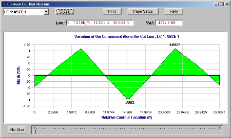
This detailed diagram will show you all the results for every section along the length of the diagram. this information may even be copied to the clipboard for use in a spreadsheet program. This can be done by selecting Copy Data from the right click menu.
Note